
We're Different

Histroy of CSS
1896년에 미국 토목기술자인 James H. Watson과 Stanley Simpson이 특허를 시작으로, CSS는 북미 지역에서 1930년대까지 주로 작은 배수로에 적용되었습니다. 1900년대 후반까지는 최대 Span(폭)을 11m까지 확장하여 소규모 교량, 통로, 군사시설물(탄약고) 등에 적용이 확대되었습니다. 2000년대부터는 Span을 23m까지 확장하여 생태터널, 광산의 Stockpile, Reclaim Tunnel, 군사시설물(격납고) 등에 적용 범위를 넓혔습니다. 2014년부터 2016년 사이 DAEDOTech®는 초대골형 파형강판(EXSCor) 연구개발과 상용화에 성공함으로써 최대 Span을 40m까지 확대할 수 있었습니다. Span 확대와 함께, 과거에 적용할 수 없었던 광산트럭인 CAT 797F(약 620톤), EURO LM71 등의 최대 하중을 충분히 견디며, 다단계 공정의 콘크리트 구조물에 비해 경제성, 안정성, 시공성에서 충분한 경쟁력을 갖추게 되었습니다. 또한, 초대골형 파형강판(EXSCor®)은 한국(KDS, KCS)�은 물론, 미국 AASHTO LRFD, ASTM A796M의 설계 기준에 따른 공법 및 제품으로 등재되어 있습니다.
General Infomation
파형강판은 공장에서 일정한 강도의 파형을 생성하여 가공 전 강재보다 강성을 크게 향상시킵니다. 표준형(피치: 150mm, 깊이: 50mm)은 92배, 대골형(피치: 381mm, 깊이: 140mm)은 842배, 초대골형(EXSCor)(피치: 500mm, 깊이: 237mm)은 2,466배의 강성 증가를 보입니다. 제조 과정은 다음과 같습니다:
-
강성이 증가한 파형강판을 제작하여,
-
도면의 요구사항에 맞는 곡률을 가공하고,
-
조립 시 사용할 볼트홀을 생성합니다.
-
내구성 향상을 위해 용융아연도금 처리를 하여 현장에 반입합니다.
-
현장에서는 고장력 볼트로 연결하여 조립을 완료합니다.
-
볼트 주변과 파형강판의 겹칩부(기와장 조립 부위)에 방수 처리를 한 후,
-
구조계산서 및 시방서에 명시된 요구사항에 따라 뒤채움재료를 넣고 다져서 구조물을 완성합니다.


Solution Improvement
파형강판 설계시 안정성 확보를 위한 가장 중요한 요소인 이음부실험, 휨실험 및 박스형태의 헌치부 실험등을 수행하였으며, 다양한 소재 (KS D 3503 fy:275MPa, fy: 315MPa, fy:450MPa)와 두께 (1.6mm ~ 10mm)의 실험을 통한 검증 값을 적용하여, 강구조 설계기준(KDS 14 31 10: 2017: 국토교통부), 도로공사 표준시방서 (KCS 11 40 10: 2016: 국토교통부), 국방, 군사시설기준(DMFC 4-10-70: 2009: 국방부)을 만족하며, 해외수출인 경우에는 ASTM A796M, AASHTO M167, AS/NZS 2041.1:2011을 만족하여 수출하고 있습니다.


Bolt Seam Strength

Bending Moment

Hunch_Bending Moment

또한, 전세계적으로 4개 업체만 생산을 하는 초대골형 (EXSCor: Pitch: 500mm, Depth 237mm)을 생산, 상용화 함으로써 기존의 대골형 (Pitch: 381mm, Depth 140mm)과 비교시 강재의 소요량은 8~9%만 증가시켜, 약 3배의 단면 2차 모멘트의 강성을 확보함으로써 경제적이며, 보다 안정성이 확보된 파형강판의 생산능력과 엔지니어링 능력을 보유하고 있습니다.
Hunch_Bending Moment Lab. Motion Picture
3 Times Increased

Typical Section Library Service
우리는 초대골형(EXSCor®)의 강성증가와 함께 Span대비 단면비율(Rise Ratio)을 최적화하여 토목현장의 특성상 많은 현황 변경에 대하여 고객이 원하는 단면을 능동적으로 제공하게 되었습니다. Span 2m부터 최대 40m까지 각 Span을 기반으로 각각 8~9개의 최적의 단면비율 (30%~ 85% / Box shape: 20%~65%)을 구성하여 약 440개의 단면표준도 (Typical Section Library)를 보유함으로써 고객에게 적시에 CAD파일로 제공할 수 있습니다. 물론, 각각의 단면에 대한 파형강판 수량과 최적 토피고에 대하여 제공함으로써 초기 계획 수립 및 설계시에 OCT결과와 함께 제공을 합니다. *단면 계획 수립시 Typical Section Library에 대한 요청을 DAEDOTech® 엔지니어에게 상의하여 주시길 바랍니다.


Solution Engineering Service
당사는 OCT Program (Optimization Comparison Table)을 통하여 One-Stop 서비스를 제공합니다. OCT Program은 스마트폰 (Android Version)과 Web 기반의 프로그램으로 당사의 모든 엔지니어들은 현장의 요구 조건에 대하여 ①395,872개의 Library Database를 통하여 ➞ ②실시간으로 최적의 단면을 선정하며, ➞ ③최적의 단면 선정시에는 강종, 뒷채움재료와 뒷채움 다짐도의 선택(보조기층재, 노상토, 다짐율 95%, 90%, 85%)을 통한 현장 조건을 충분히 반영을 하여, ➞ ④파형강판의 두께(m당 무게 산정을 통한 가격비교 가능), 구조물의 안정성 (각국의 기준에 준하는 안전율 표기)을 즉각적으로 제공받을 수 있습니다. ➞ ⑤또한, 콘크리트 기초에 대한 발생응력값을 제공함으로써, 구조물 계획을 수립시에 단지 파형강판 공사비 비교가 아닌, 전체적인 공사비에 대한 파형강판의 안정성이 확보된 최적화된 엔지니어링을 제공합니다. OCT Program 활용을 통한 최적의 구조물을 계획후에는 구조계산서, 설계도면, 물량산출서가 자동으로 산출되는 내부 프로그램을 통하여 파형강판에 관한 일체의 엔지니어링 서비스를 제공합니다.


Optimizing Comparison Report
*Section, Stability, Weight
Based on Web Version

FEA
①편토압 조건의 구조물, 토피고 과다하게 높은 �경우와 현장조건의 특수성인 있는 경우에는 ➞ ②3D, 2D Modeling 전산해석 (FEA: Midas GTX, ABAQUS, Midas Civil, CANDE)을 통하여 뒷채움 단계별 파형강판 구조물의 발생모멘트, 축력 및 변위를 예측하여 구조계산에 반영하는 엔지니어링 서비스를 제공합니다.


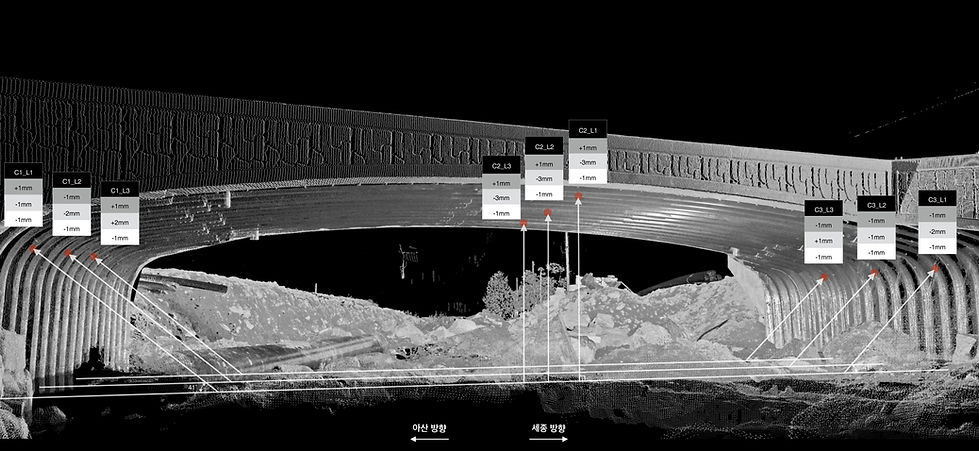
3D Scan Monitoring
당사는 최신기술인 3D Scanning system (Leica® 3P, Cyclone®, TrueView®) 기술도입을 업계 최초로 도입하여 구조물의 모니터링 서비스를 수행하여, 이를 통하여 3차원으로 뒷채움 단계 및 완�공후의 변위, 최종 토피고에 대하여 ±3mm이내로 조사업무를 제공합니다.


BIM (Building Information Method)
세계최초로 BIM을 파형강판 계획 단계부터 적용함으로써 고객이 3차원으로 현장 계획 및 세밀한 부분까지 충분히 이해를 돕고자 했으며, 상세 설계 시에 투입되는 재료와 비용에 대하여 정확히 산출함으로써 Error를 최소화 하였습니다. BIM 상세설계의 단계를 LoD350*Level of Development이상으로 설계 됨에 따라서, 적용되는 모든 소재의 객체속성이 제공됩니다. 이를 통하여 향후 유지관리 부분까지 고려한 설계방식입니다. 또한, 시공단계별 상세한 자료를 제공함에 따라서 현장에서의 오차를 없도록 했으며, On-Line Viewer를 통하여 고객들에게 Smartphone과 PC로 공유하고 있습니다.


